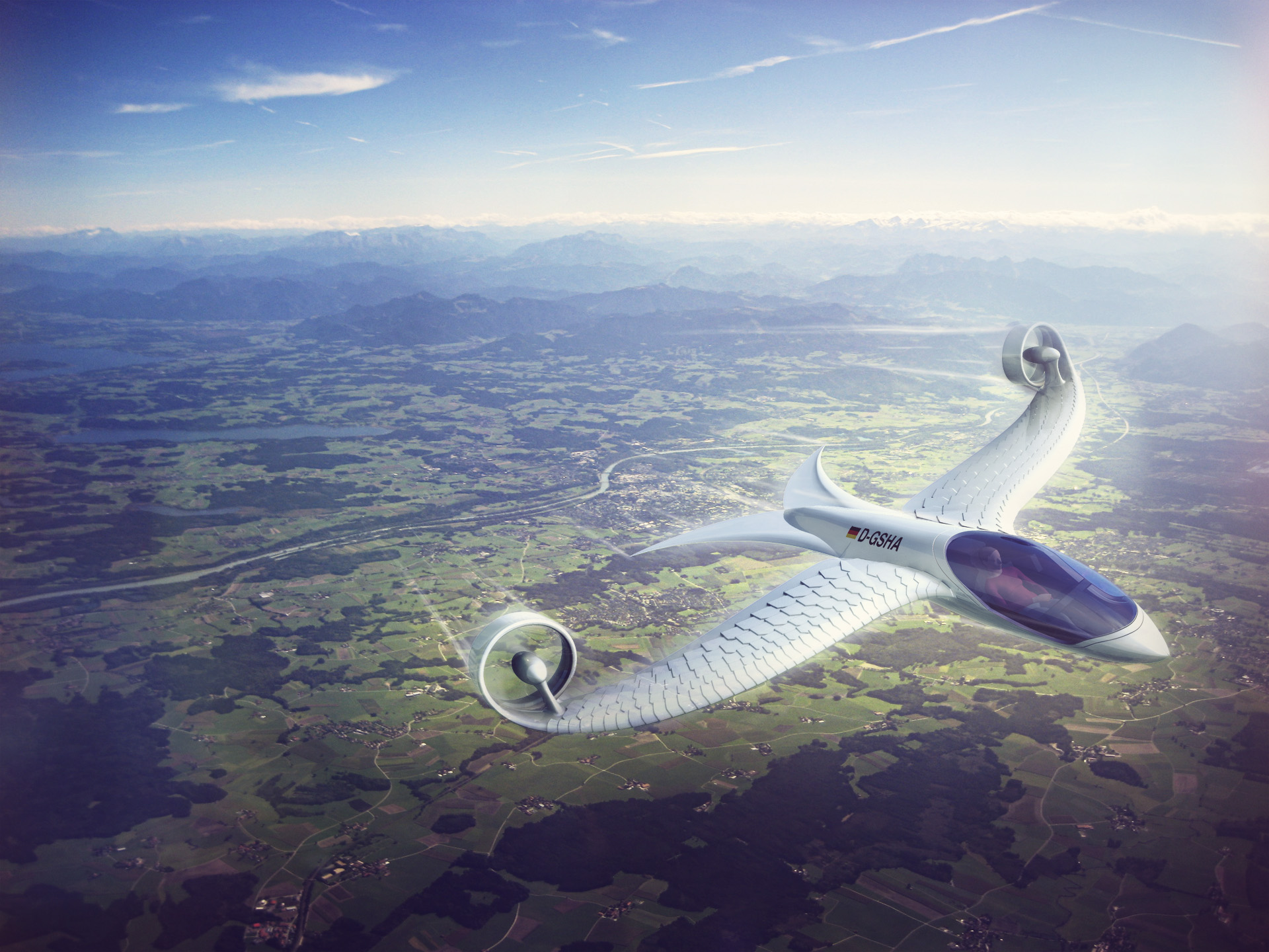
The wing that
doesn't stall.
A bird-feather-inspired surface that keeps flow attached up to ~50° angle of attack, where conventional wings collapse. Proven across four years of wind-tunnel and field testing, and now reproduced from first principles in a coupled fluid-structure simulation.
The wing that doesn't stall.
A bird-feather-inspired surface that keeps flow attached up to ~50° angle of attack. Proven in four years of wind-tunnel and field testing, and now reproduced from first principles in a coupled fluid-structure simulation.
01 — The unsolved regime
eVTOL's hardest problem isn't hover or cruise. It's the transition between them.
During transition, the aircraft rotates from thrust-borne vertical flight to wing-borne horizontal flight — passing through a wide range of high angles of attack at low airspeed. This is exactly where conventional fixed-wing surfaces stall: the boundary layer separates, lift collapses, and control authority degrades at the worst possible moment.
The aircraft must then power through the gap on thrust alone — driving up energy demand, weight, noise, and certification risk. Lilium, Vertical Aerospace and fixed-wing transition UAVs all face the same constraint: a wing that loses lift precisely where the envelope needs it most. The problem is aerodynamic, not merely propulsive.
02 — The principle
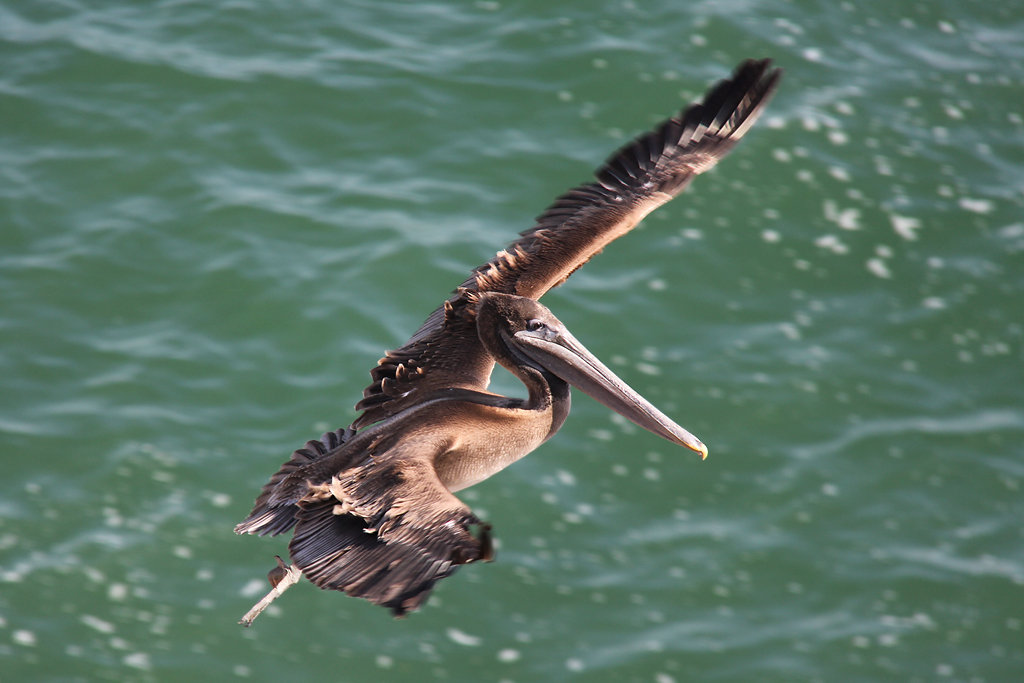
Birds solved this long before aviation existed.
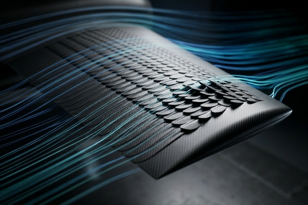
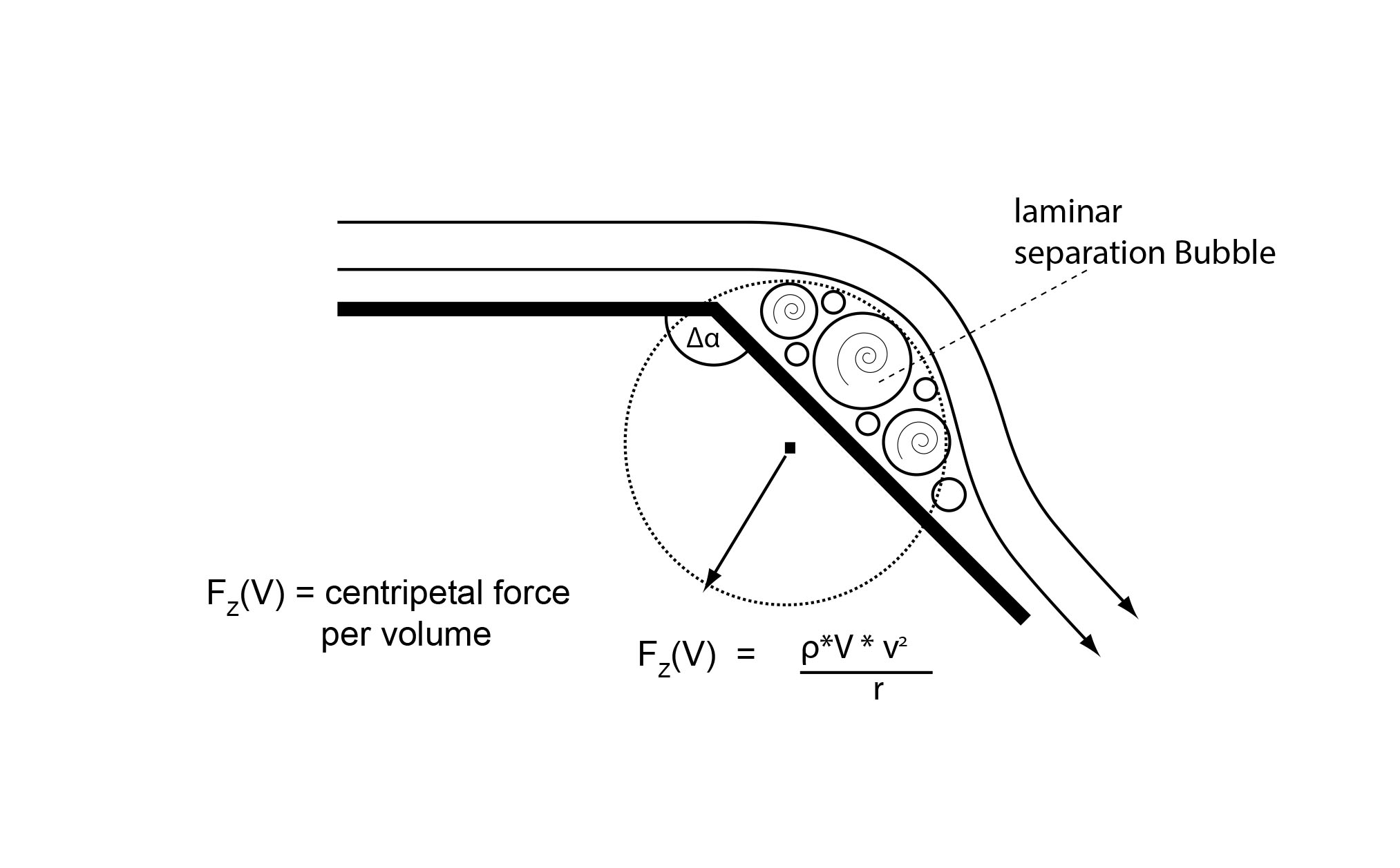
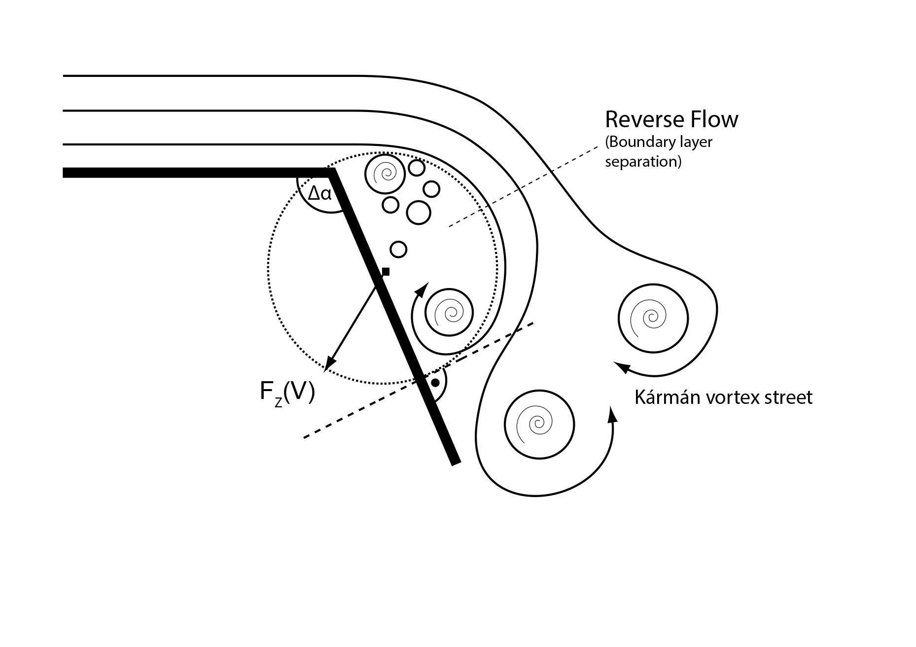
At high angles of attack — landing flares, gusts, slow flight — the covert feathers on a bird's wing lift against the flow. These raised feathers block reverse flow into the separating boundary layer and keep the flow attached far beyond where a rigid surface would stall. AFAX reproduces this mechanism, cladding the entire profile in small, passively hinged scale-like elements.
Full-surface, not a single flap
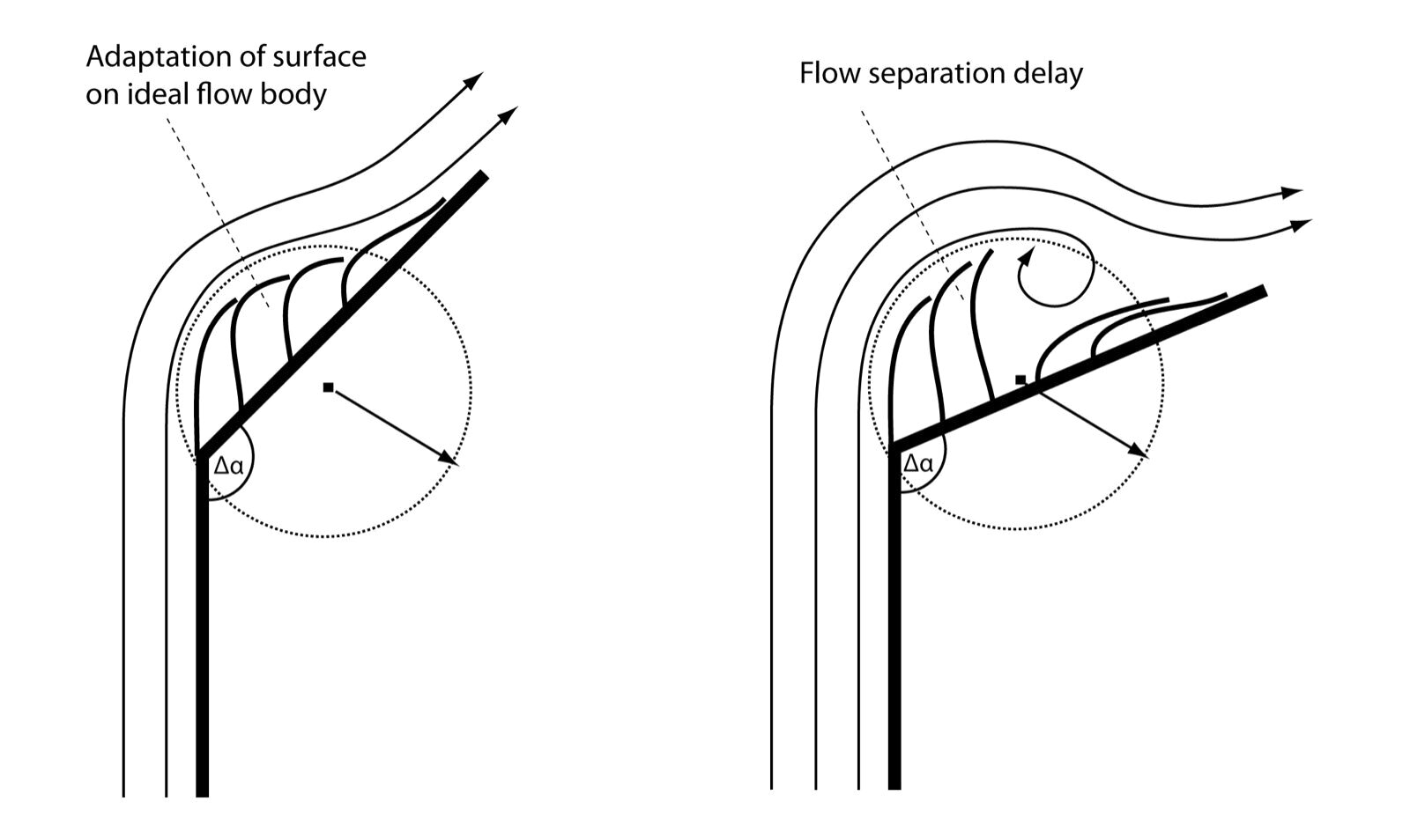
Unlike earlier single rear-flap work, cladding the whole profile lets the flow shape the body element-by-element — no local bulge, no unfavourable deformation.
A passive Krüger effect
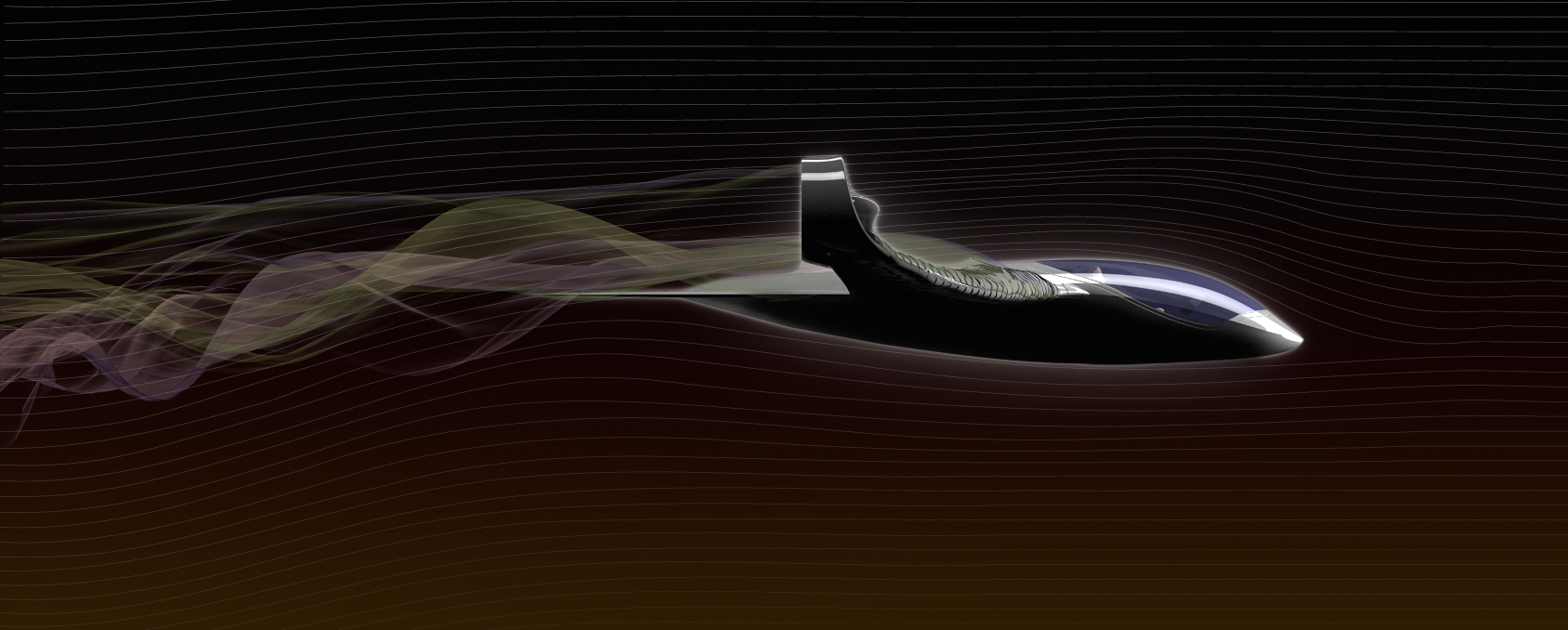
At very high incidence the stagnation point moves onto the lower surface — scale elements there flip up against the flow, a passive area increase with no actuators or electronics.
Zero active failure modes
No sensors, no actuators, no control electronics. The surface responds to the flow alone — a decisive advantage for a safety-critical, certification-bound application.
The conventional profile
The aeroflexible profile
The upper-surface suction peak is what generates lift. Keeping it from collapsing is the whole game — read the underlying lift principle →
03 — Measured performance
Lift where rigid wings have already given up.
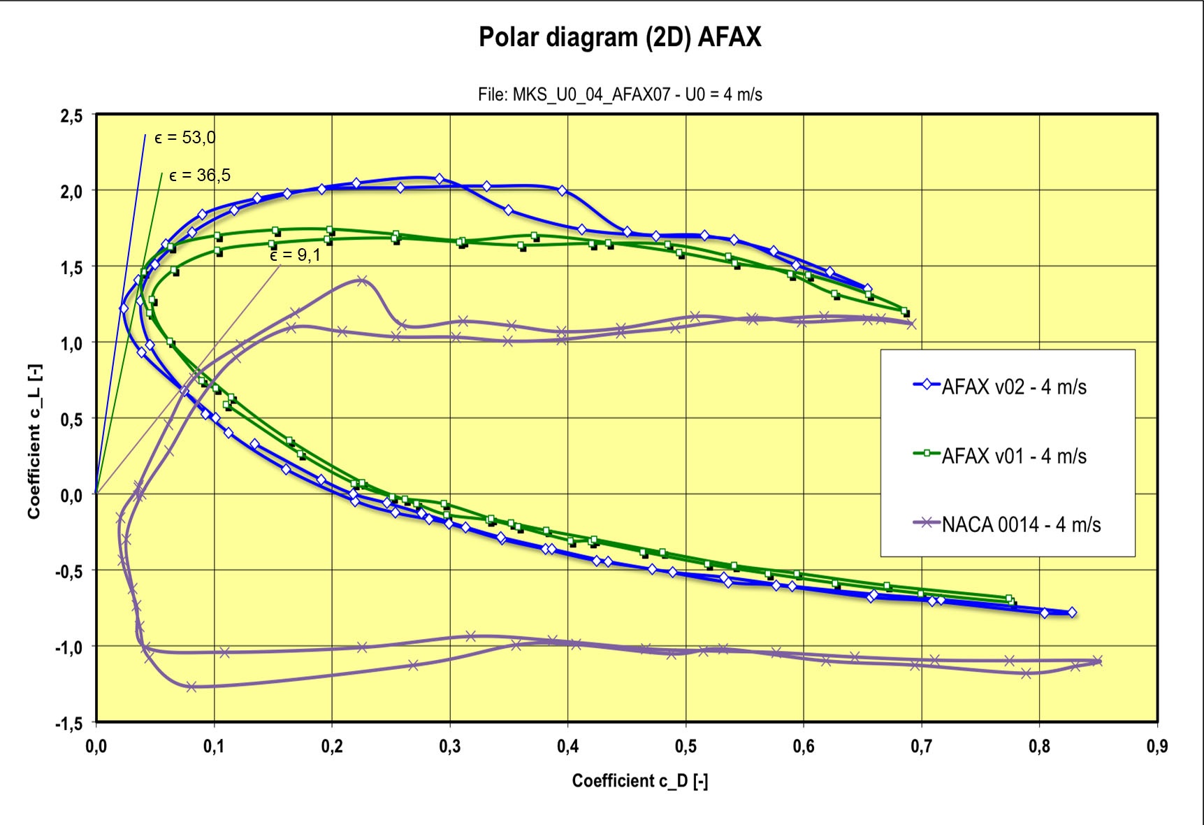
Wind-tunnel and field measurements across several profile generations, plotted as a lift-vs-drag polar against a rigid reference.
Peak lift advantage at the high-incidence operating point, vs. the rigid reference profile.
Net lift advantage at the 40° optimum — inside the transition envelope.
Angle of attack up to which flow stays attached — well beyond conventional stall.
High-incidence advantage
The aeroflexible profile keeps producing lift up to ~50° — reaching +60% at the maximum and a net +23% at the 40° optimum.
A small, honest cruise penalty
At low angles of attack the adaptive profile shows slightly lower lift than the rigid reference — a deliberate trade for the high-incidence gain.
A counterintuitive drag result
Despite thickening the profile, the surface measured a better drag coefficient than expected — an effect that warrants dedicated further study.
Transparency note: these are AFAX's own wind-tunnel and field measurements, presented as measured results — not independently peer-reviewed findings. The cruise-drag result in particular invites independent replication.
04 — Applications
One principle, wherever flow separates.
Passive flow control applies to any surface that stalls under adverse or fluctuating conditions. The lead focus is eVTOL and autonomous flight — but the physics is domain-agnostic.
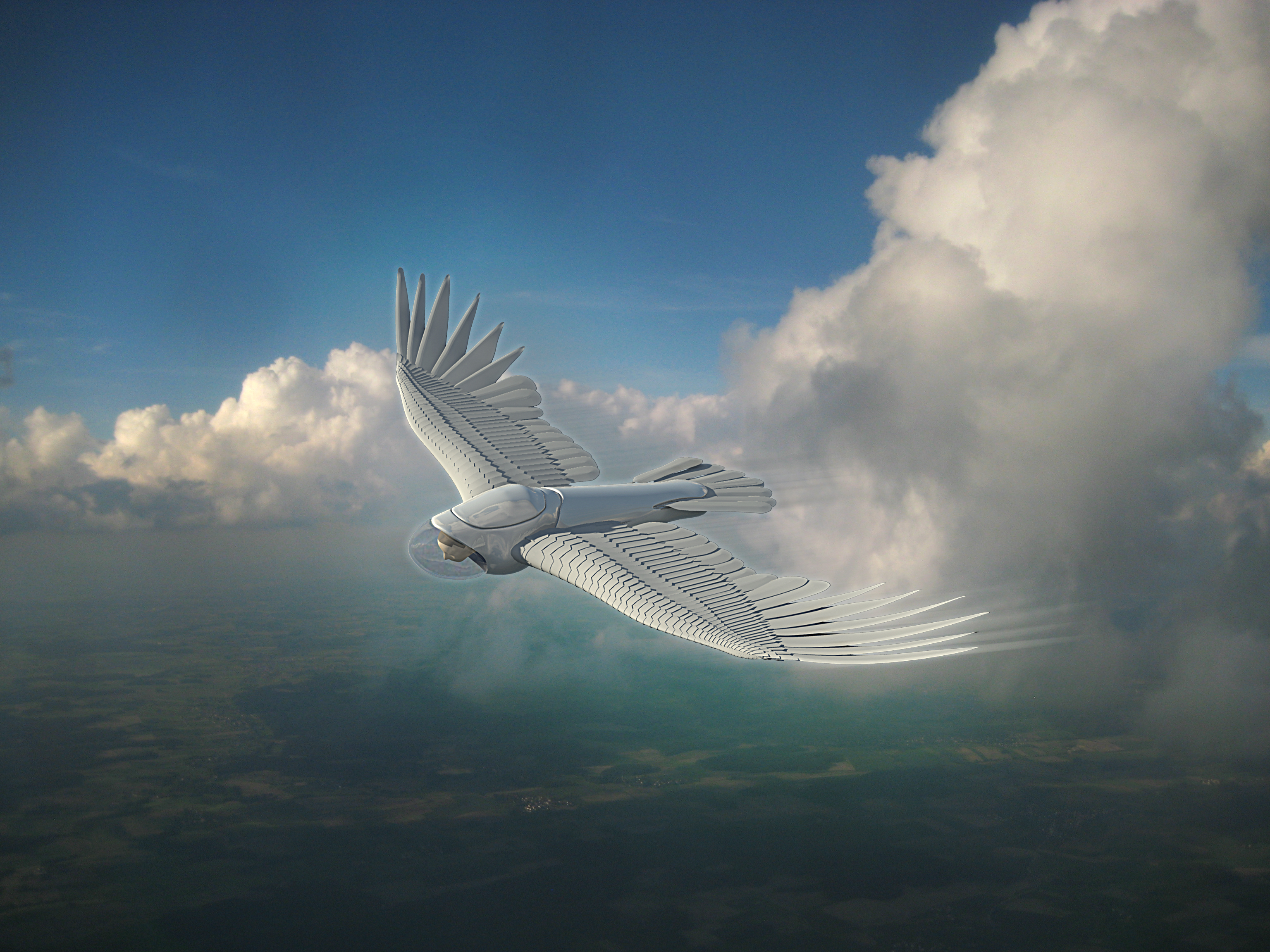
Lead focus
eVTOL & autonomous flight
Extends the safe envelope through vertical-to-horizontal transition — exactly where winged VTOL configurations stall today.
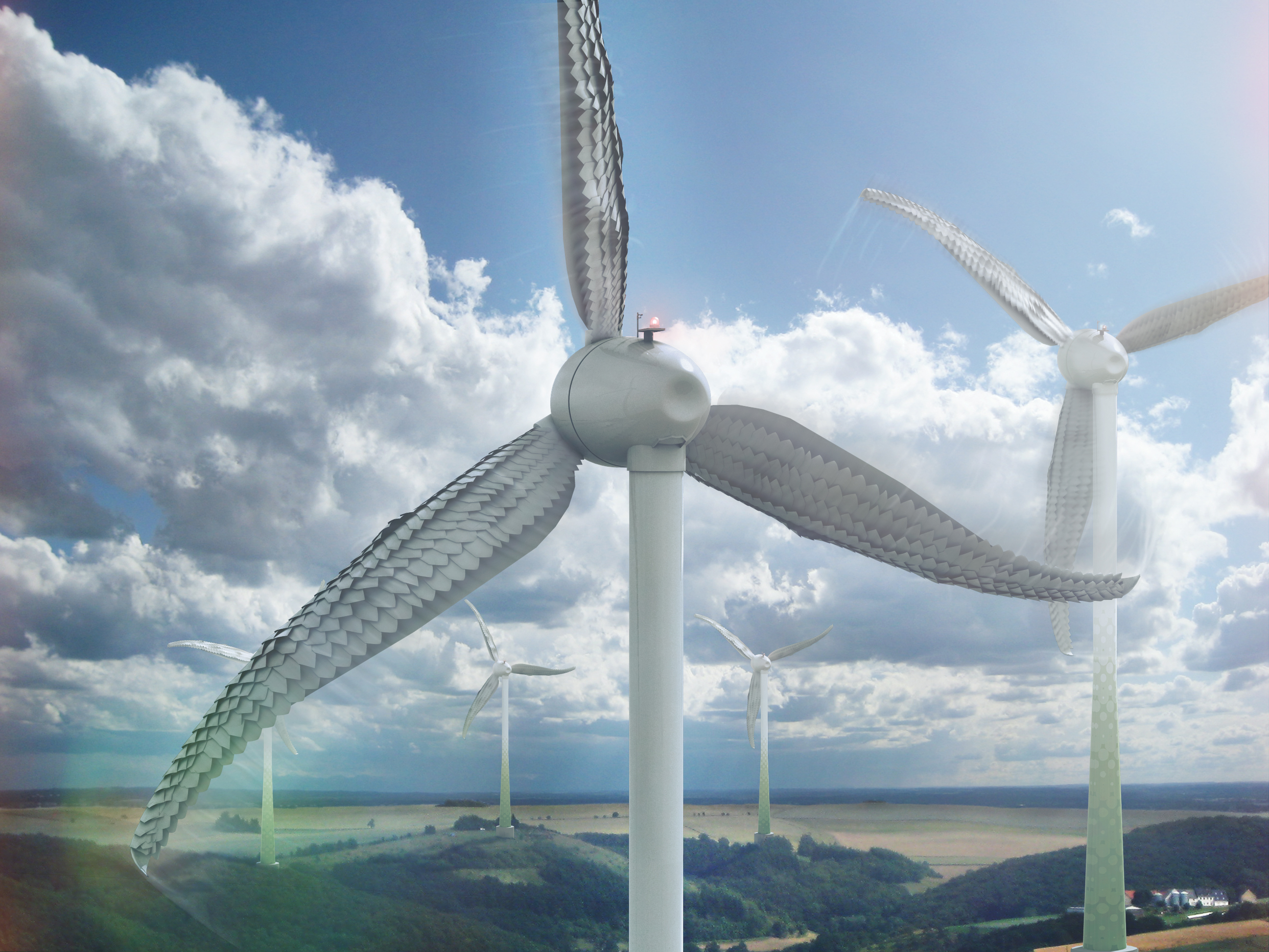
Proven MVP
Wind energy
Faster startup and a higher power curve on turbulent inland wind — the domain where the technology was first field-validated.
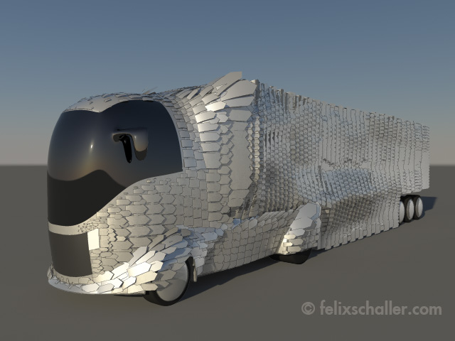
Adjacent
Heavy transport
Drag reduction on trucks and trailers, where separated wakes behind bluff bodies waste energy at highway speed.
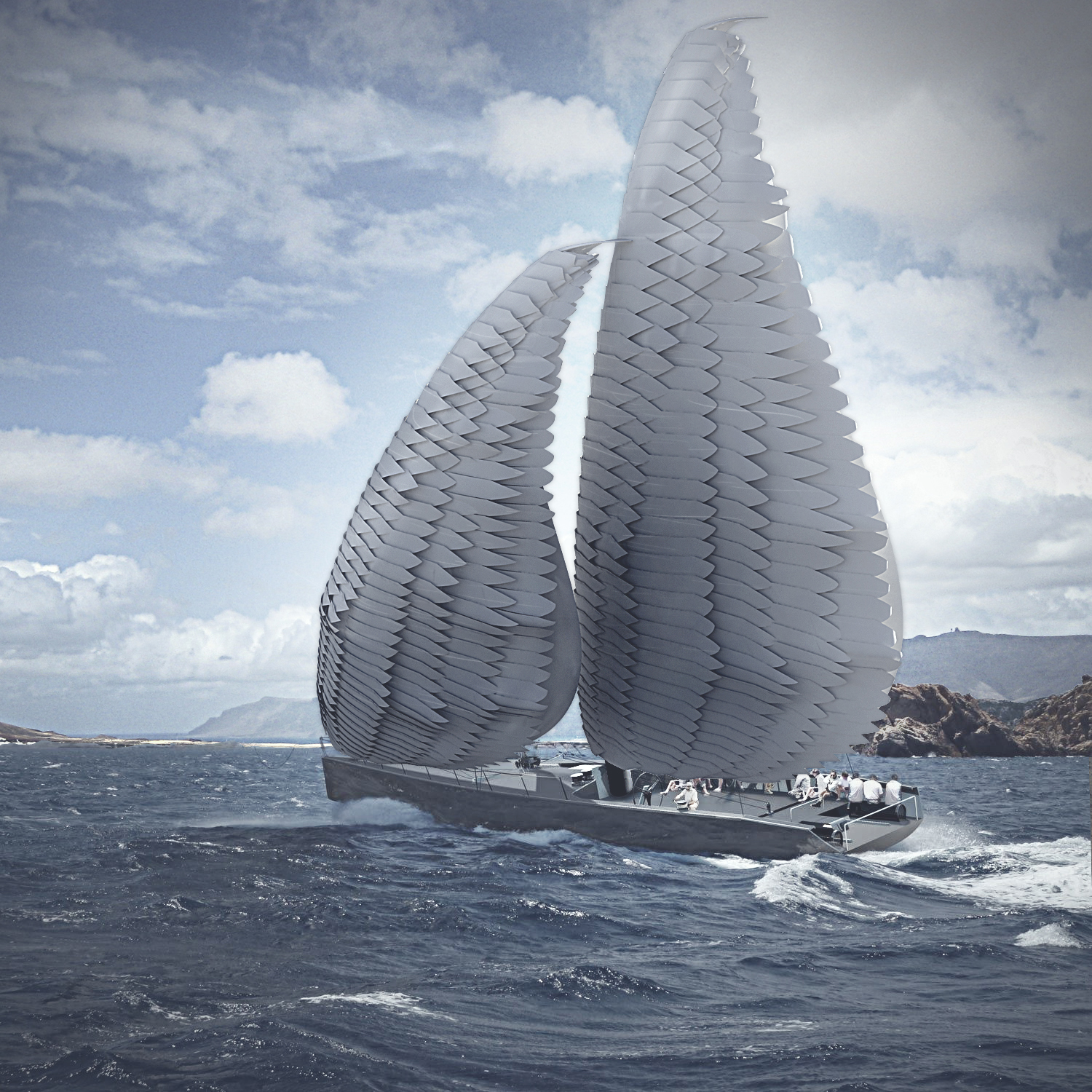
Marine
Sails & foils
Adaptive lift on sails, rigid wings and hydrofoils operating across a wide, shifting range of incidence.
05 — Field validation
Proven in the field on a wind turbine. The physics held — the 20-year material case did not.
On the advice of TU München's startup incubator (UnternehmerTUM), the technology was first taken to market through wind energy — lower certification overhead, a proof-of-concept stepping stone before aviation.
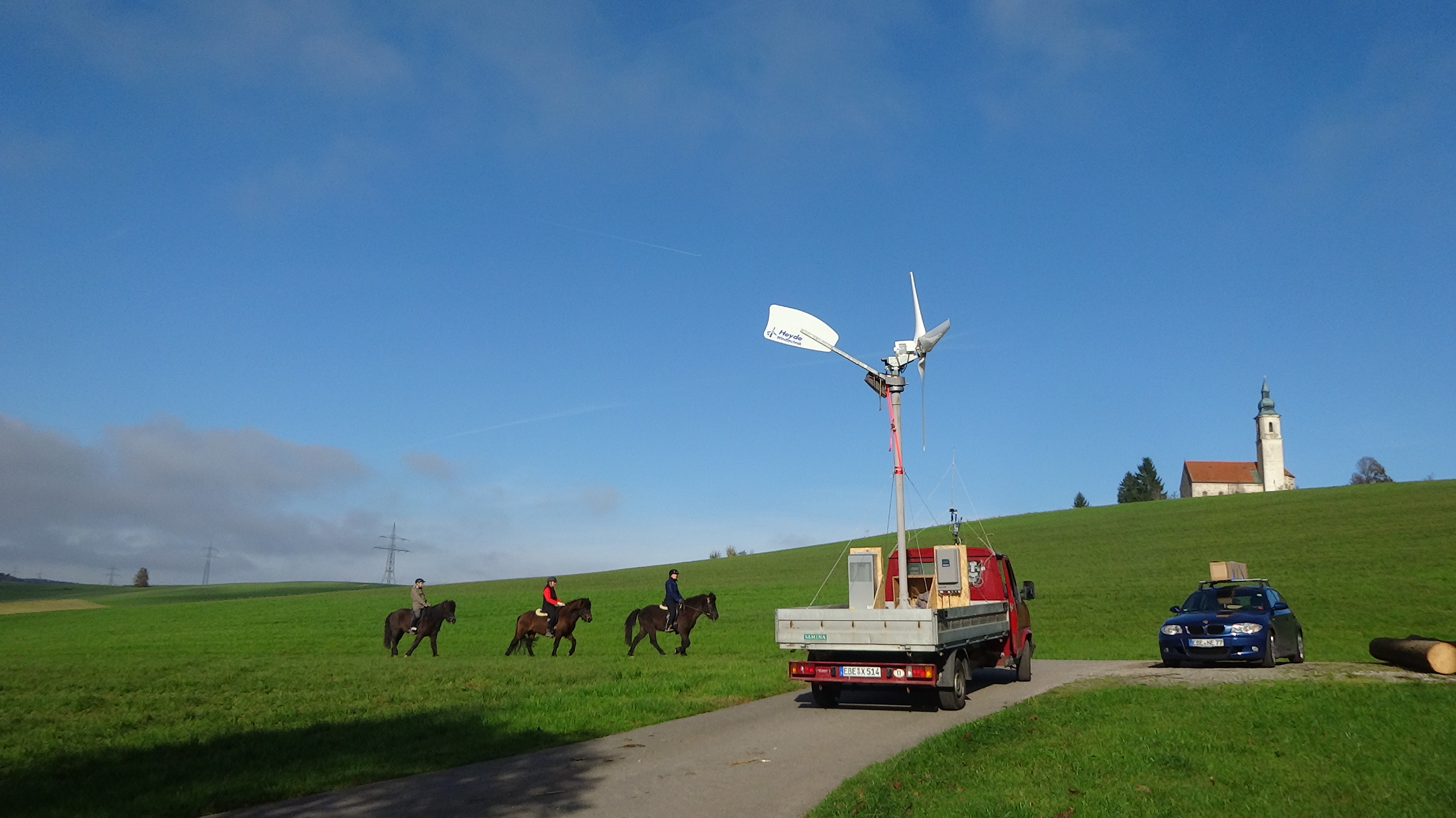
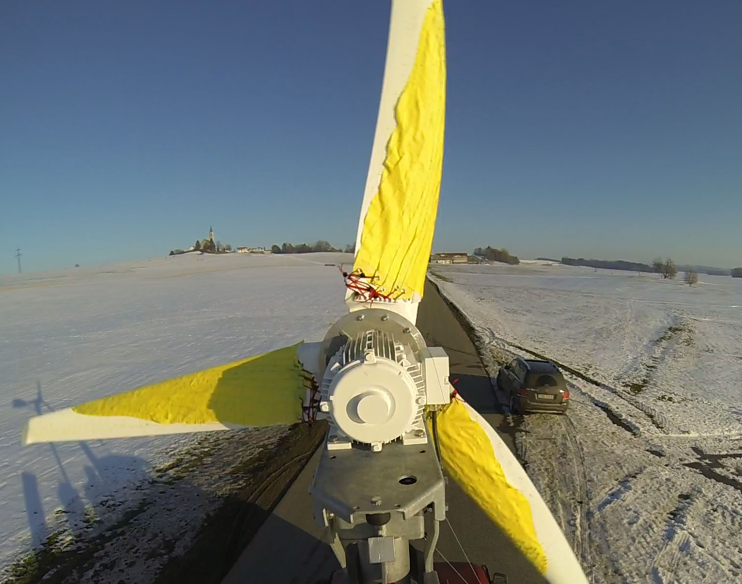
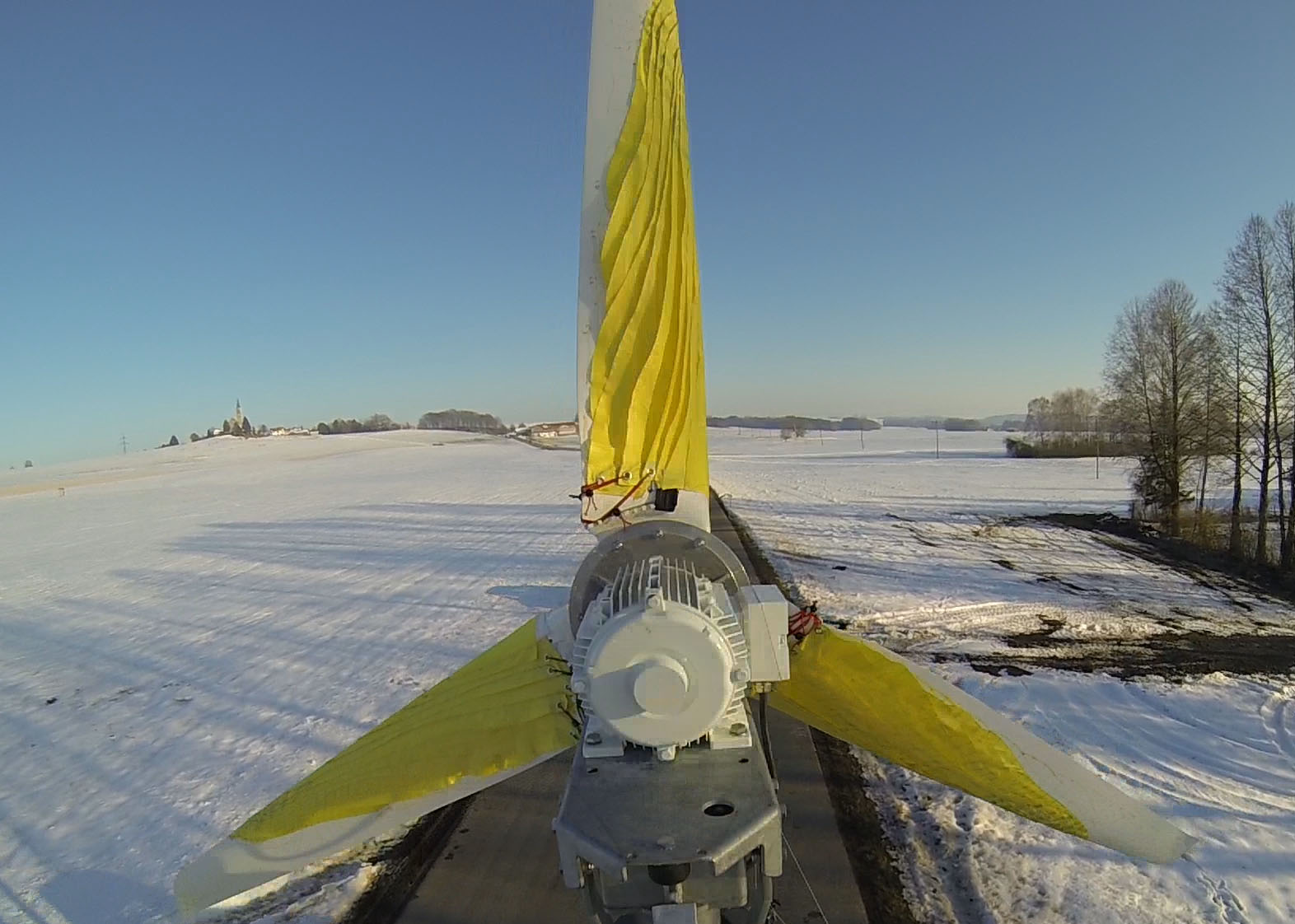
A mobile rig — a sub-3.5-tonne flatbed truck carrying a 1.5 m-radius turbine — enabled direct back-to-back comparison of modified and standard rotor blades under real wind.
- ✓Startup time to rated speed roughly halved.
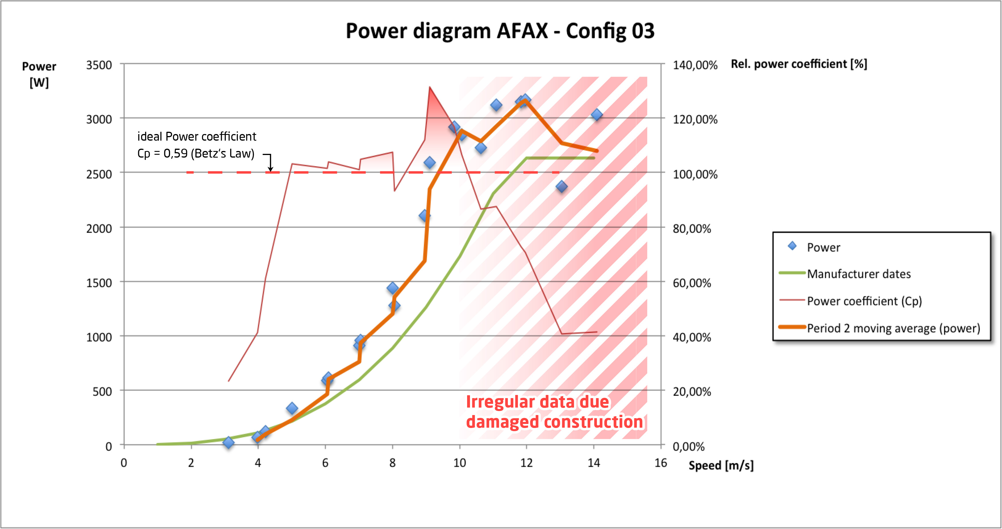
- ✓Power curve shifted upward across the operating range.
- ✓Improved behaviour under turbulent, fluctuating inland wind.
The technology worked; the business case didn't. A rotor cladding must last ~20 years under UV, ice and load — no economically viable material met that bar. The wind path closed for material reasons, not physical ones. That constraint does not exist for eVTOL, where aircraft renew every 2–5 years.
06 — Scientific lineage
A question the field keeps returning to.
Markus Schatz
First academic study of passive rear-flap separation control.
AFAX
First full-surface implementation, validated in wind-tunnel and field tests.
TU Berlin
Related research (DBU report AZ-33893-01) — the question stays scientifically live.
Dr. Wolfgang Send
Independent 2D polar (ex-DLR); scientific lead of the Festo SmartBird ornithopter.
The founder
Felix Schaller
Dubai, UAE · Munich, Germany
Four years of prototyping and testing built application and fabrication know-how that was never publicly documented — and stays with the founder. AFAX is being reactivated with a sharpened focus: away from wind energy, toward VTOL and autonomous aircraft, long-term as an application domain within the XIXUM universe.
07 — Status & outlook
Reactivating a proven principle for the regime that still isn't solved.
The transition problem AFAX addressed in 2012 remains unsolved across the eVTOL industry today. Modern additive manufacturing now makes the scale-element geometry producible in ways that weren't feasible for the original 2012–2016 prototypes — removing a key fabrication bottleneck.
Let's make transition a solved problem.
For eVTOL programs, aerospace investors and R&D partners: request the technical overview, or open a conversation about integration and licensing of the application know-how.