We simulated the wing that doesn’t stall.
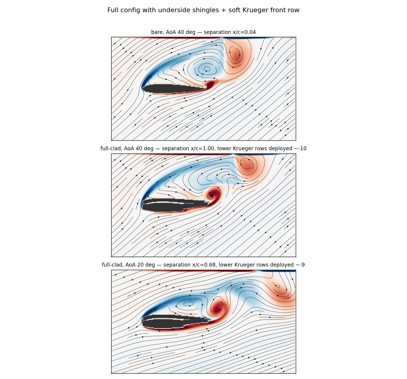
The wind tunnel showed that the covert-feather cladding postpones stall. A 2D fluid–structure simulation now shows why — the flexible feathers deform under the flow, catch the incipient reverse flow in pockets, and hold the boundary layer attached where a rigid wing has long since separated.
01 — From wind tunnel to simulation
The measured effect was never in doubt. The open question was the mechanism.
Four years of wind-tunnel and field testing (ANIPROP, Dr. Wolfgang Send) established the result: a full-surface, passively hinged covert-feather cladding keeps a NACA 0014 attached to roughly 50° angle of attack, with about +60% maximum lift and +23% at 40° over the rigid baseline. The physical device works.
What the experiments deliberately left open is the computational picture — a solver that reproduces the passive deformation and shows, cell by cell, how the surface adapts to the flow. That is the leg we built: a coupled 2D fluid–structure model of the feathered profile.
02 — The mechanism
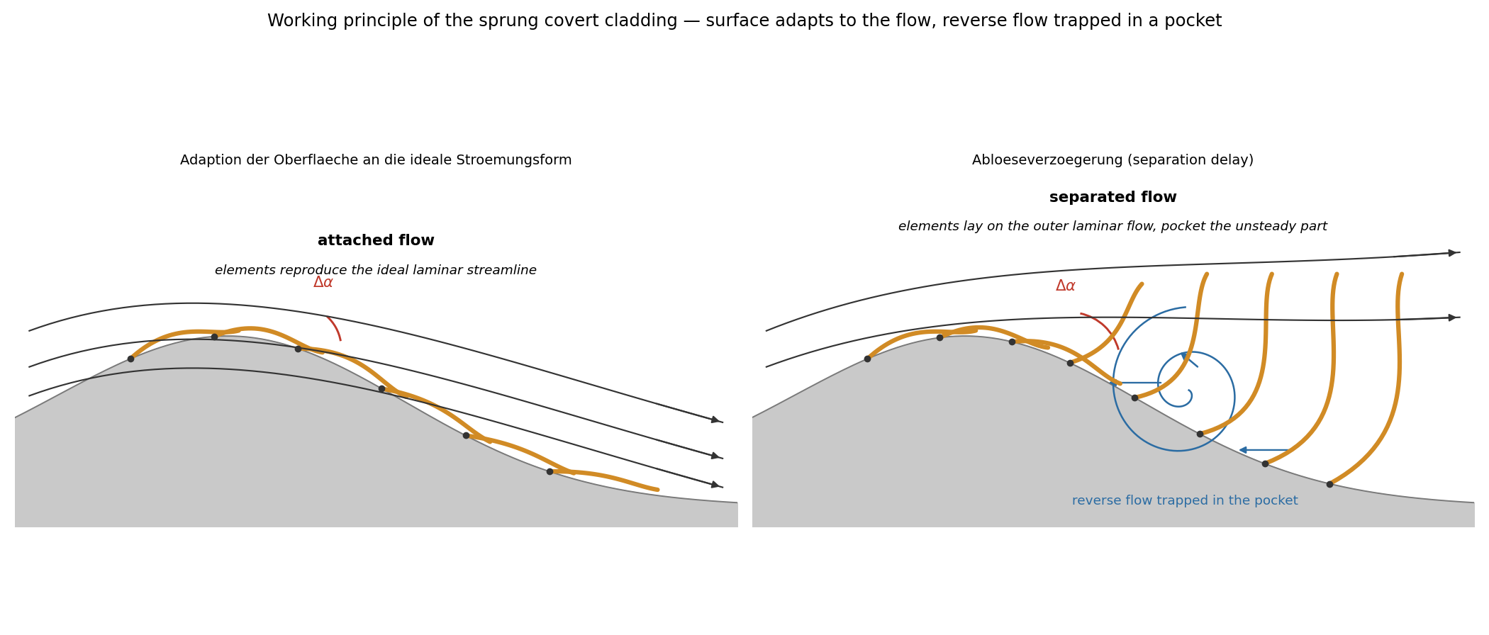
Attached flow: the surface traces the ideal streamline. Separating flow: the feathers open into pockets that trap the reverse flow.
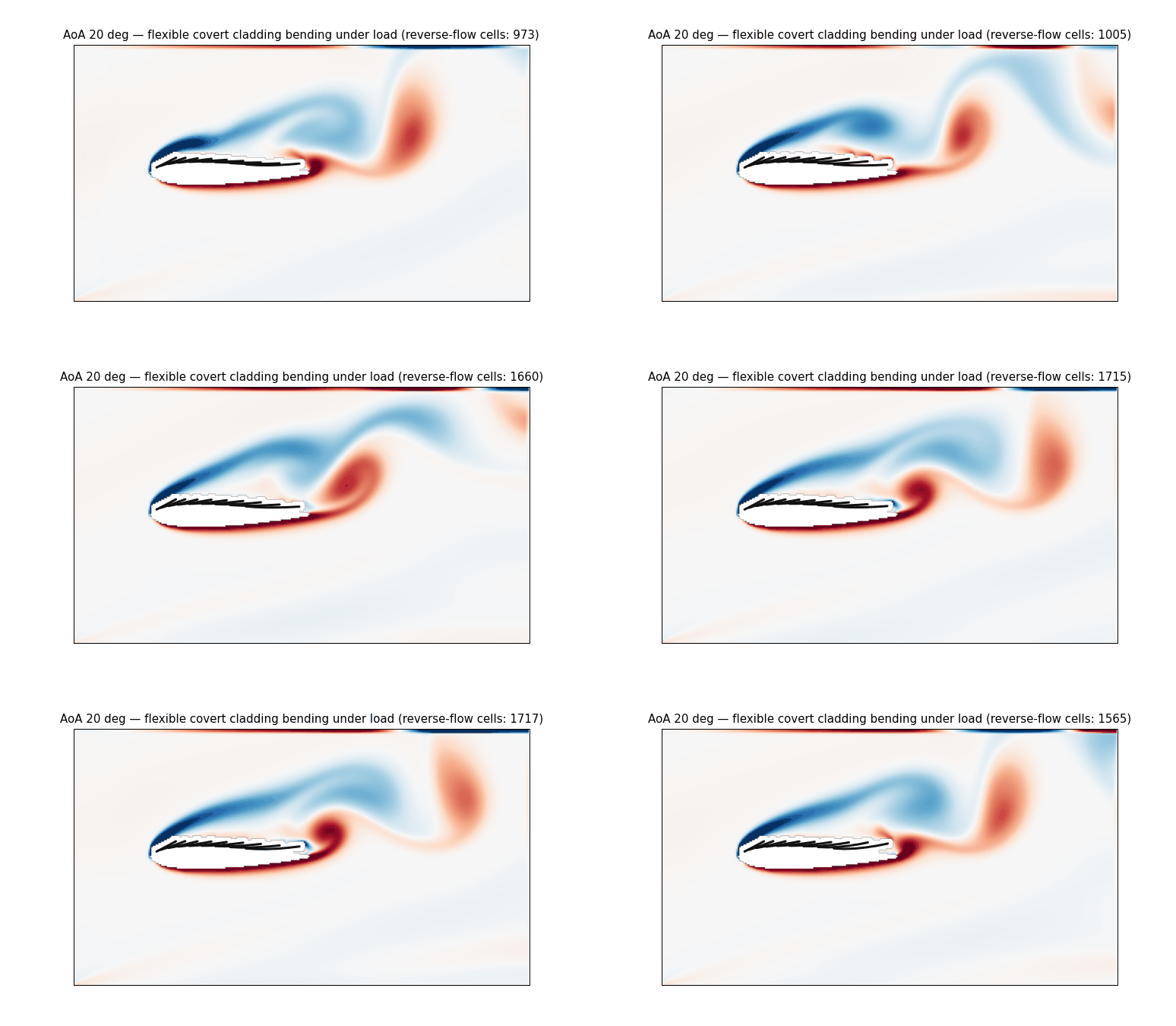
Under attached flow the elements lie flush and reproduce the ideal laminar contour. As separation begins, the still-laminar outer flow stays on top while reverse flow tries to creep upstream underneath — and the sprung feathers lift just enough to lay against the outer shear layer and seal that reverse flow into a pocket, so it can no longer propagate forward. Separation is delayed by compartmentalising the very region that would otherwise stall the wing.
03 — The model
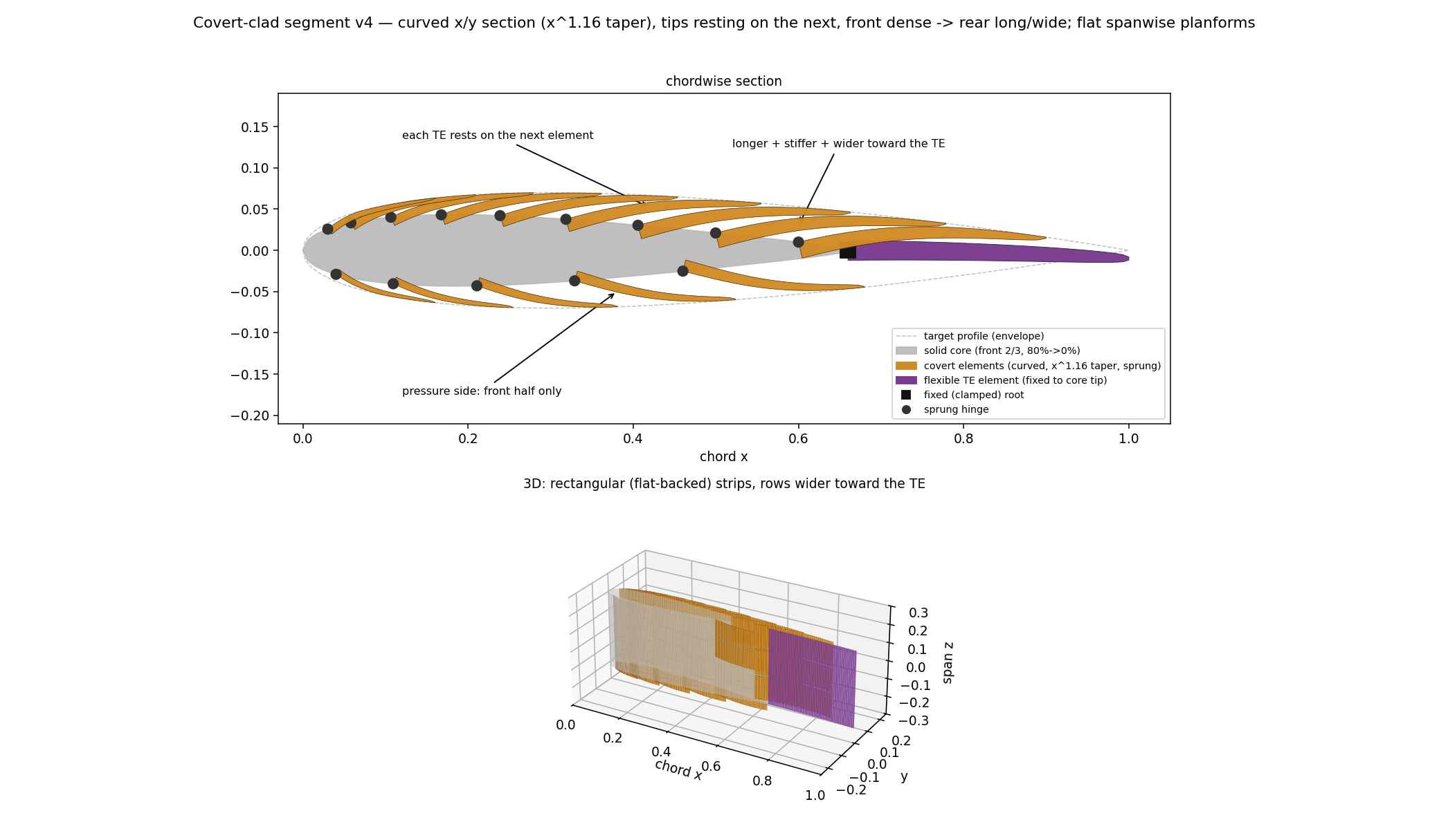
Every feather is a flexible, tapered beam — not a rigid flap.
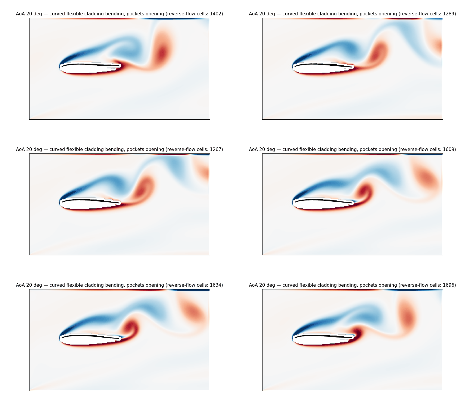
The compliance that matters is elastic bending, not a hinge flopping over. Each covert element is modelled as a clamped Euler–Bernoulli beam whose area moment of inertia tapers along its length as (1 − s/L)1.16 — the exponent that bends a loaded beam into a true circular arc rather than kinking at the root.
The rows are subdivided and graded: dense, soft, sensitive at the front, progressively stiffer toward the trailing edge. They sit on a core that is carved back from the contour, so the shingles and a single fixed, flexible trailing edge are what form the aerodynamic profile. On the pressure side, a soft front row acts as a passive Krüger flap that deploys on its own once the stagnation point shifts behind it at high incidence.
The overlapping feather edges are not cosmetic: they are the catch that lets the flow trigger the deployment. A perfectly smooth skin has nothing for the flow to grip — the overlap is functional.
04 — The result
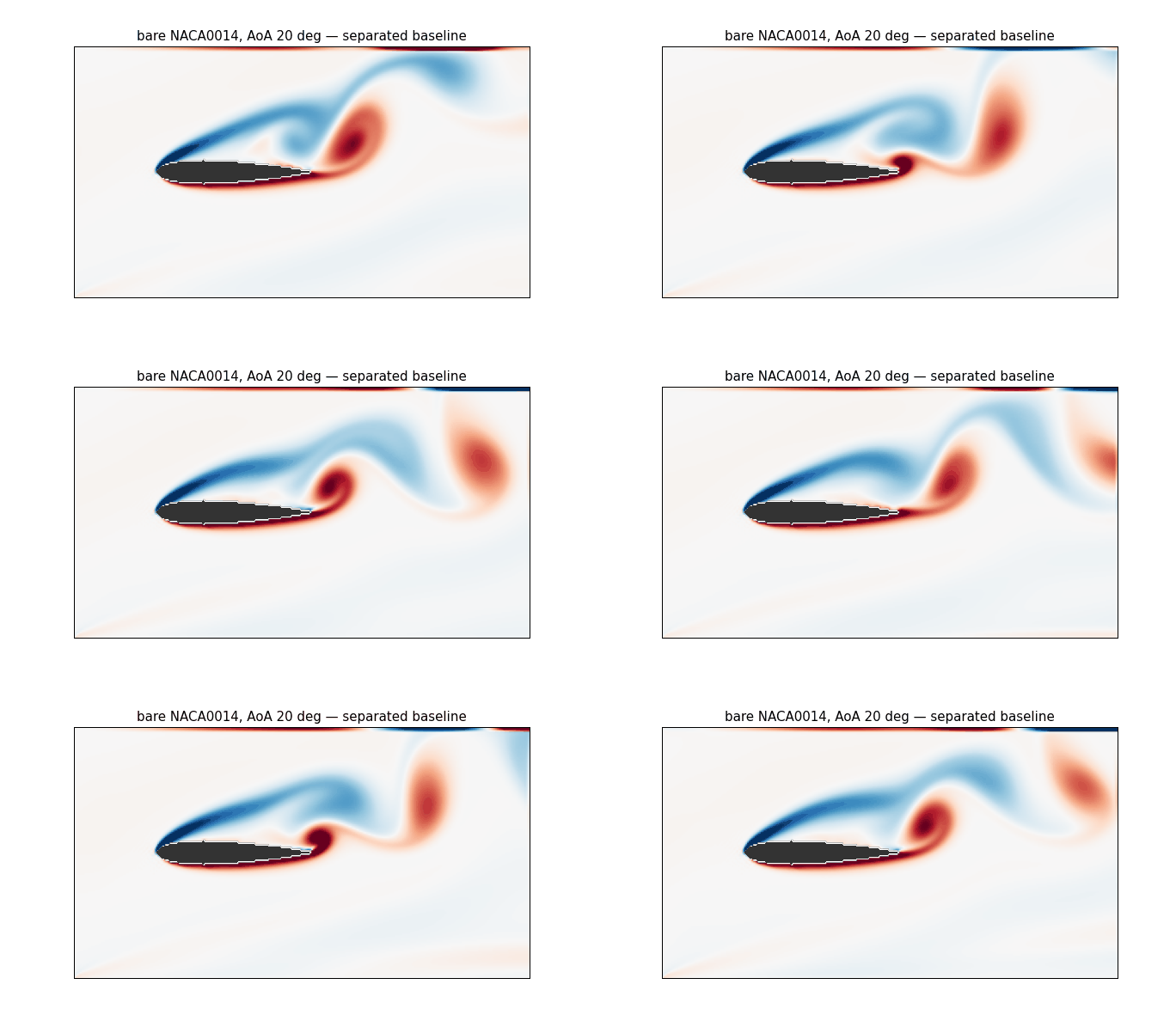
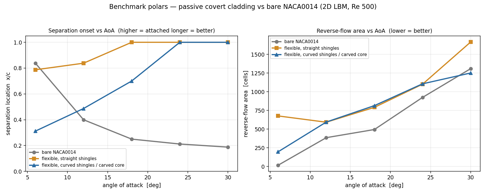
A rigid wing separates ever earlier as it pitches up. The feathered wing holds on.
In the coupled runs the feathers deploy passively, exactly where the flow starts to separate, and the separation line moves back toward the trailing edge. The animations below are the live coupling: flow on the left, the feathers bending and the pockets opening as the simulation advances.
Method & limits
What the model is. A 2D D2Q9 lattice-Boltzmann flow solver coupled, in a partitioned scheme, to a per-feather tapered Euler–Bernoulli beam. The feathers load from the local pressure field, bend, and re-enter the flow each coupling cycle. Every configuration is measured against the identical NACA 0014 at rest, so the comparison isolates the cladding, not two different profiles.
What it is not. The Reynolds number is held modest for solver stability, so the flow is laminar and absolute lift and drag are not yet quantitative. The robust, reported quantities are the separation-onset location and the reverse-flow area — the right measures for a stall-delay device. High-resolution runs at higher Reynolds number are in progress.
What it shows. The simulation reproduces the passive mechanism and the separation-delay trend of the wind-tunnel campaign, from first principles and without tuning to the measured polars. It is the computational companion to the experimental result, not a substitute for it.
Full aerodynamic background: Passive Reverse-Flow Control through Full-Surface Covert-Feather Cladding — An Enabling Bridge Technology for the eVTOL Transition Regime (AFAX technical paper).
A passive wing that keeps its lift through the transition regime.
Experiment and simulation now point the same way. Let’s talk about where it fits — eVTOL, rotors, or high-lift surfaces.